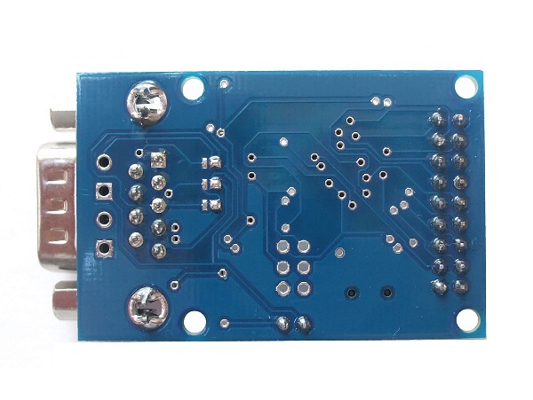
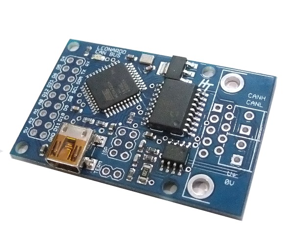
Leonardo CAN BUS board
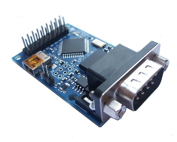
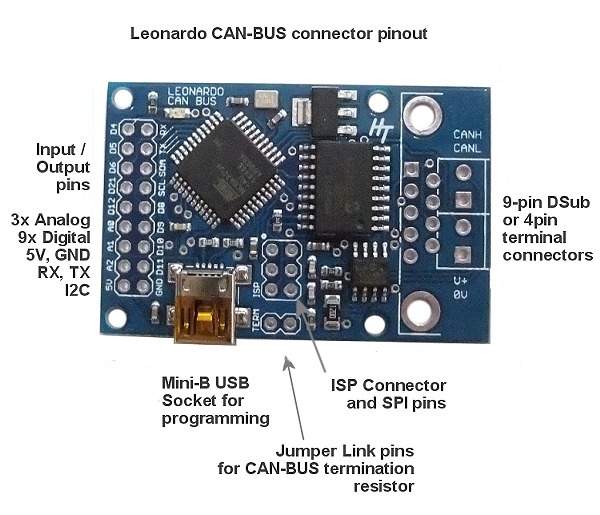
This Arduino Leonardo based CAN-BUS controller board contains an ATmega32U4 microcontroller with the Arduino Leonardo bootloader installed and uses the Microchip MCP2515 CAN controller with MCP2551 CAN transceiver. CAN connection is via a standard 9-way male d-sub socket for use with an OBDII cable or via a 4-way terminal connection.
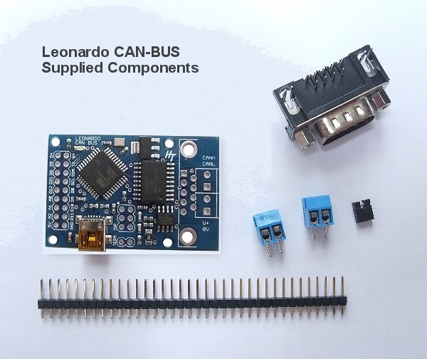
The Leonardo CAN-BUS board is supplied fully tested but with the header pins, 9-pin d-sub socket and terminal connectors unsoldered as not all customers need these attached.
- ATmega32U4 microcontroller with Arduino Leonardo bootloader
- USB Mini-B socket for programming (no programmer required)
- CAN v2.0B upto 1 Mb/s
- High speed SPI Interface (10 MHz)
- Standard and extended data and remote frames
- CAN connection via standard 9-way d-sub connector or 4-way terminal
- On-board 5V voltage regulator allows power to be supplied through d-sub connector (max 16V)
- LED indicator
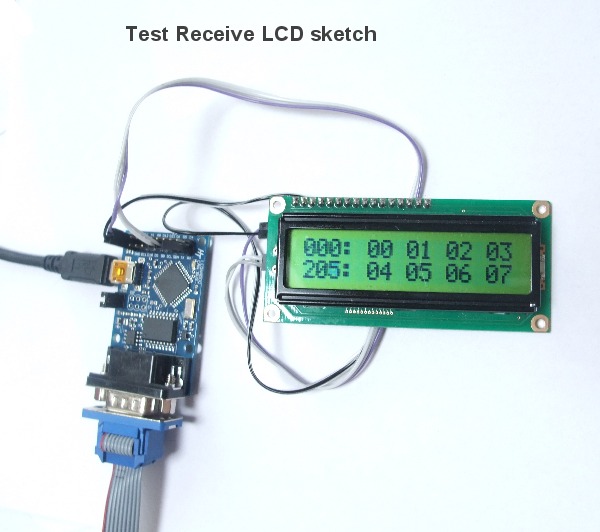
- Arduino Library and example programs
- Board size: 51mm x 33mm (2in x 1.3in)
Documents relating to the CAN-Bus Shield:
- Datasheet (MCP2515)
- Datasheet (MCP2551)
- OBD-II Parameter IDs
- Leonardo CAN-BUS Schematic
- Arduino MCP2515 CAN-BUS Library
- USB-CAN firmware for Linux gs_usb This is the gs_usb_leonardo project that adds native Linux SocketCAN capability.
- YouTube Video – Great video for getting started reading the CAN-BUS in cars
Termination Resistor
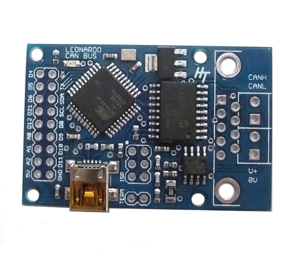
According to the Can-Bus specification, a 120ohm terminating resistor should be placed across the CANH and CANL lines at each end of the Can-Bus. This resistor is built onto the board and can be connected using the jumper link to connect the two pins labelled TERM. This should not be required when connecting to a vehicle OBDII system.
Example Programs
First download and install the Arduino CAN-BUS library. The example programs from this library are designed for the Sparkfun Arduino Can-Bus shield which has slightly different pin connections, so the example programs won’t work without modification.
The MCP2515 CAN BUS chip uses SPI for communication with the microcontroller and the Chip Select pin needs to be set correctly.
In the example programs, the chip select pin needs to be changed to 17. I.e.
const int SPI_CS_PIN = 17;
Also, some example programs use an led. There is an led on the board but it is pin D23, so change the code to
const int LED = 23;
ATmega32U4 Fuse settings
If you reprogram the bootloader onto this board or use a programming language other than Arduino, you must set the L Fuse to 0xBF. This activates the CLK OUT pin which is used by the MCP2525 chip. Without this fuse setting, the Can Bus chips on the board will not work.
OBDII cables
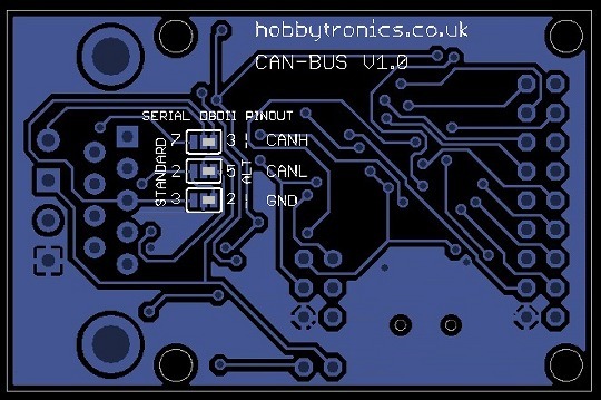
There are a couple of different wiring schemes for OBDII cables. We have 3 solder jumpers on the rear of the board which will allow you to set the Serial DB9 connector to one of 2 cable wiring schemes. The OBDII cables, sold by Sparkfun use the alternate wiring scheme, and so this is how to setup the boards for this. To change to the Standard scheme, solder the centre tab to the left tab (STANDARD).


